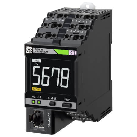
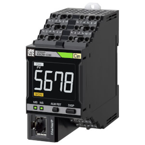
K6CM-ISM
Zustandsüberwachungsgerät für Motoren – Isolationsüberwachung
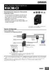
Der K6CM-ISM überwacht den Isolationswiderstand als Indikator für die Verdrahtungs- und die Sicherheitsbedingungen des Motors.
Sobald der Messwert unter den voreingestellten Warn- oder Alarmwert fällt, löst das System seine Ausgabe aus.
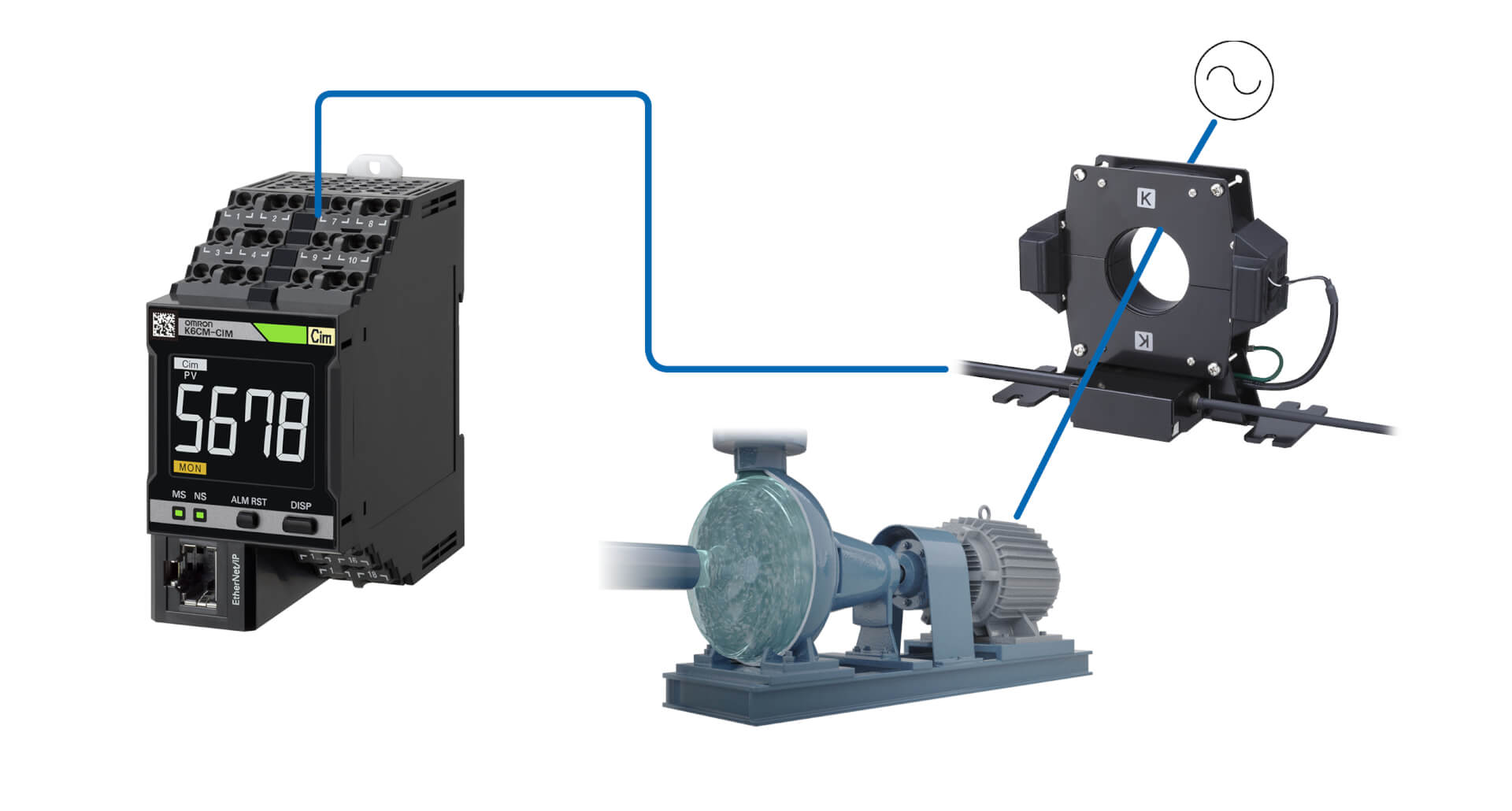
Die Installation ist sowohl in bestehenden als auch in neuen Maschinen einfach, da keine Sensoren am Motor verkabelt werden müssen: Der Stromwandler kann einfach an den Kabeln zur Stromversorgung des Motors angebracht werden, und der Controller ist für den Einbau im Schaltschrank vorgesehen.
Das Gerät kann entweder im Standalone-Betrieb eingesetzt oder in eine umfassendere Lösung integriert werden, wodurch z. B. folgende Funktionen ermöglicht werden:
- Benachrichtigungen bei Warnung/Alarm,
- Fernüberwachung
- Interaktion mit benutzerdefinierten Anwendungen und MQTT-Server.
Spezifikationen & Bestellinfo
| Produkt | Supply voltage AC | Supply voltage DC | Beschreibung | |
|---|---|---|---|---|
|
|
100-240 V | Motor Condition Monitoring, AC, 3-phase, Induction motor, Insulation resistance model, 100 to 240 VAC, Transistor control output, Push-in Plus, LCD display, Ethernet IP |
|
|
|
|
20.4-26.4 V | 20.4-26.4 V | Motor Condition Monitoring, AC, 3-phase, Induction motor, Insulation resistance model, 24 VAC/VDC, Transistor control output, Push-in Plus, LCD display, Ethernet IP |
|
Sie brauchen Unterstützung?
Wir helfen Ihnen gerne! Sprechen Sie uns an, und unsere Experten helfen Ihnen, die beste Lösung für Ihr Unternehmen zu finden.
Ihr Kontakt K6CM-ISM

Vielen Dank für Ihre Anfrage. Wir setzen uns umgehend mit Ihnen in Verbindung.
Es liegen zur Zeit technische Probleme vor. Ihre Übertragung war nicht erfolgreich. Entschuldigen Sie dies bitte und versuchen es später noch einmal. Details
Angebot für K6CM-ISM
Über dieses Formular erhalten Sie ein Angebot zu Ihrem ausgewählten Produkt. Bitte füllen Sie alle Felder aus, die diese * Markierung besitzen. Ihre persönlichen Daten werden natürlich vertraulich behandelt.
Vielen Dank für Ihre Angebots-Anfrage, die wir schnellstmöglich beantworten werden.
Es liegen zur Zeit technische Probleme vor. Ihre Übertragung war nicht erfolgreich. Entschuldigen Sie dies bitte und versuchen es später noch einmal. Details
Feature
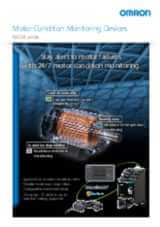
K6CM-ISM überwacht den Isolationsstatus eines Motors und warnt, wenn Veränderungen der Basis zu ernsthaften Problemen führen könnten, so dass Wartungsmaßnahmen richtig geplant werden können.
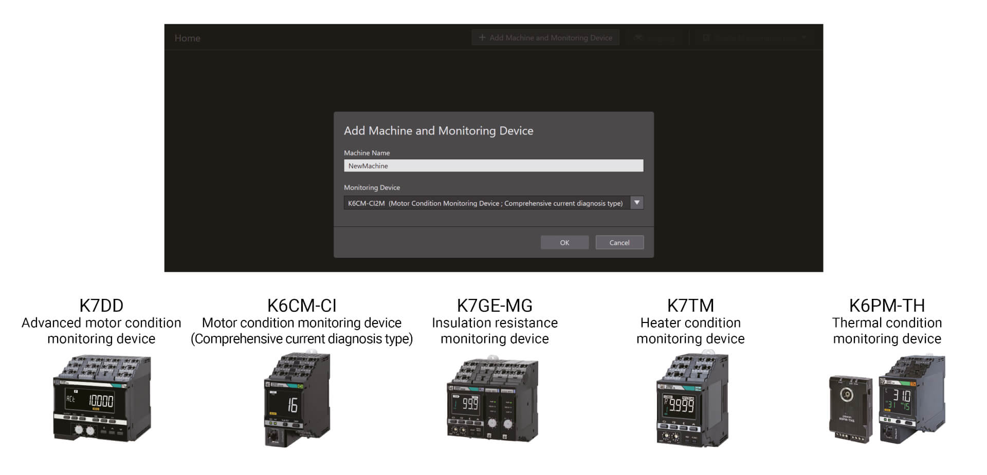
Zustandsüberwachungsgeräte können mit einem einzigen Tool konfiguriert werden
Einfache Konfiguration in drei Schritten Das Condition Monitoring Configuration Tool ermöglicht die Batch-Konfiguration einer breiten Palette von Condition Monitoring-Geräten, z. B. zur Überwachung von Motoren, Temperaturen, Isolation und Heizern. Es kann ohne spezielle Kenntnisse verwendet werden, was den Schulungsaufwand reduziert.
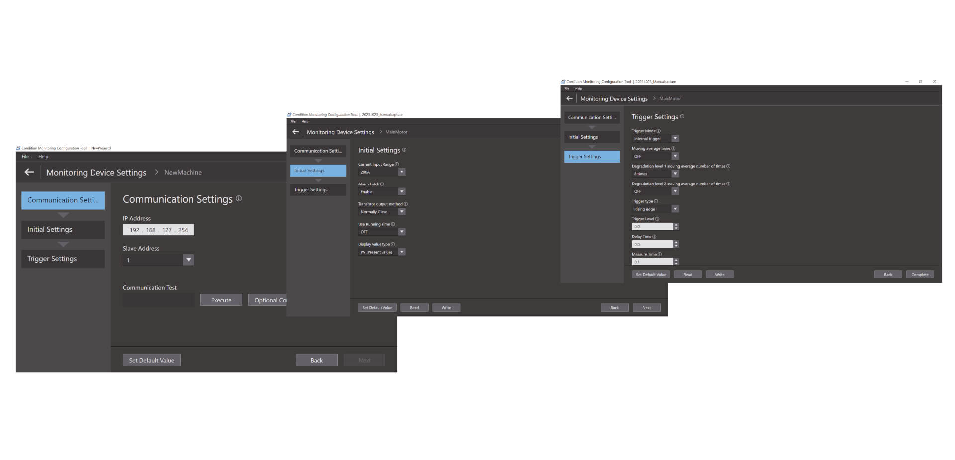
Einfache Konfiguration in drei Schritten
Einfache Konfiguration in drei Schritten Das Condition Monitoring Configuration Tool ermöglicht die Batch-Konfiguration einer breiten Palette von Condition Monitoring-Geräten, z. B. zur Überwachung von Motoren, Temperaturen, Isolation und Heizern. Es kann ohne spezielle Kenntnisse verwendet werden, was den Schulungsaufwand reduziert. Die Einrichtung erfolgt in nur drei Schritten: Einrichtung der Kommunikation, Grundeinstellungen und Trigger-Einstellung.*1 Durch die gute Bedienbarkeit erhöht das Tool darüber hinaus die Produktivität an der Anlage.
Videos

-
K6CM Motor Condition Monitoring Device
K6CM takes the burden of monitoring motors off maintenance engineers. Motors can be maintained in advance of failure due to deterioration. K6CM (comprehensive current diagnosis type) can consistently monitor motor conditions by observing the current waveform of the motor. Additionally, you can understand the motor's maintenance timing without depending on an engineer, because K6CM provides threshold value setting.
02:40
K6CM Motor Condition Monitoring Device
K6CM takes the burden of monitoring motors off maintenance engineers. Motors can be maintained in advance of failure due to deterioration. K6CM (comprehensive current diagnosis type) can consistently monitor motor conditions by observing the current waveform of the motor. Additionally, you can understand the motor's maintenance timing without depending on an engineer, because K6CM provides threshold value setting.
-

K6CM Demo Video
05:48
K6CM Demo Video
Lösungen
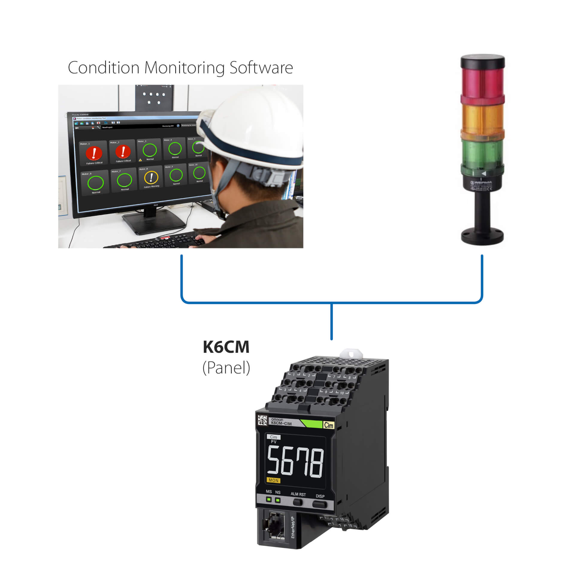
Standalone-Installation (ohne SPS)
Diese einfache Lösung ermöglicht Folgendes:
- Überwachen des Motorstatus über die integrierte LED oder die Condition Monitoring Software
- Einrichten des Controllers über die im Lieferumfang des Geräts enthaltene Condition Monitoring Software
- Verbinden des K6CM mit beliebigen externen E/A-Geräten (digitaler Ausgang)
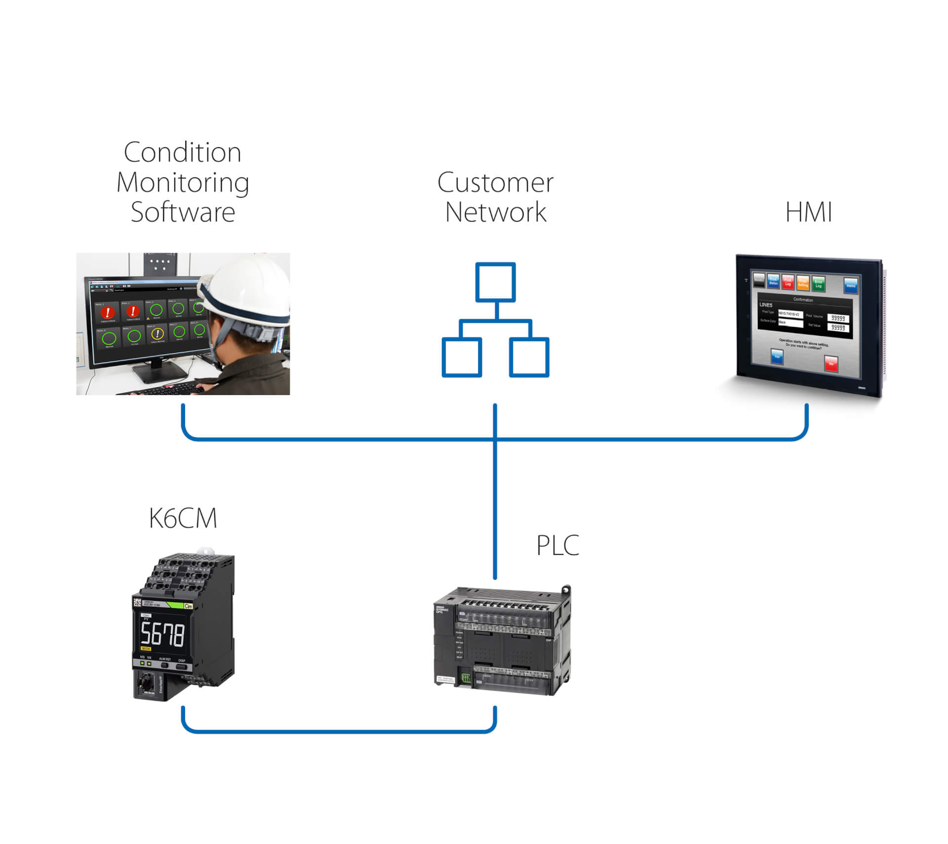
Standalone-Installation (mit SPS)
Diese Lösung ermöglicht zusätzlich zur vorherigen Lösung Folgendes:
- Überwachen des Motorstatus über die Condition Monitoring Software, die auf einem PC ausgeführt wird, der über eine SPS angeschlossen ist
- Auslösen von Aktionen über die SPS im Anschluss an Warnungen/Alarme, die vom K6CM erkannt wurden
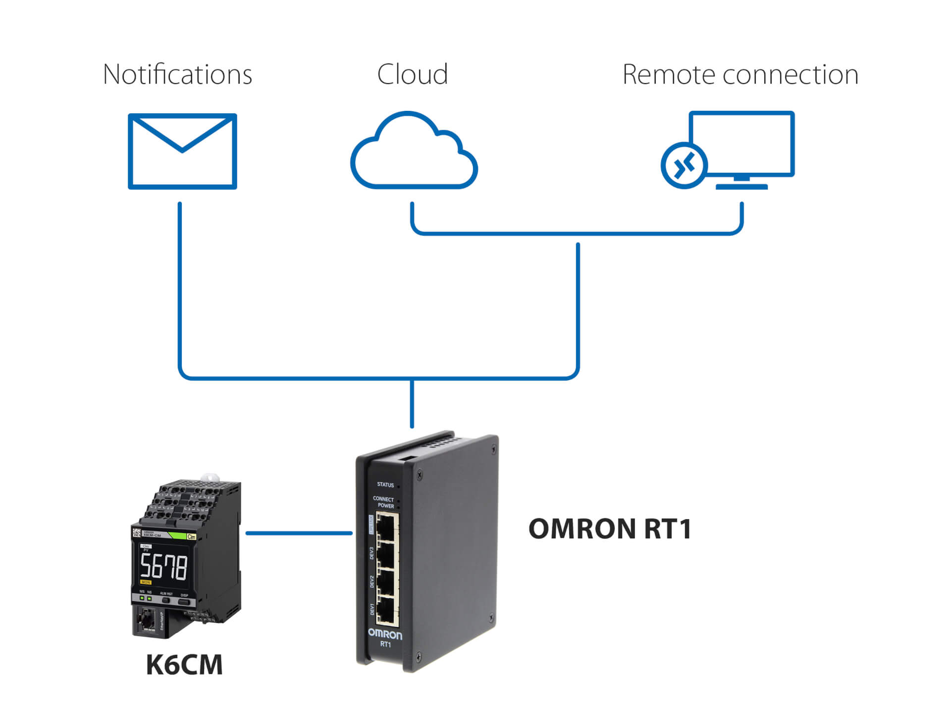
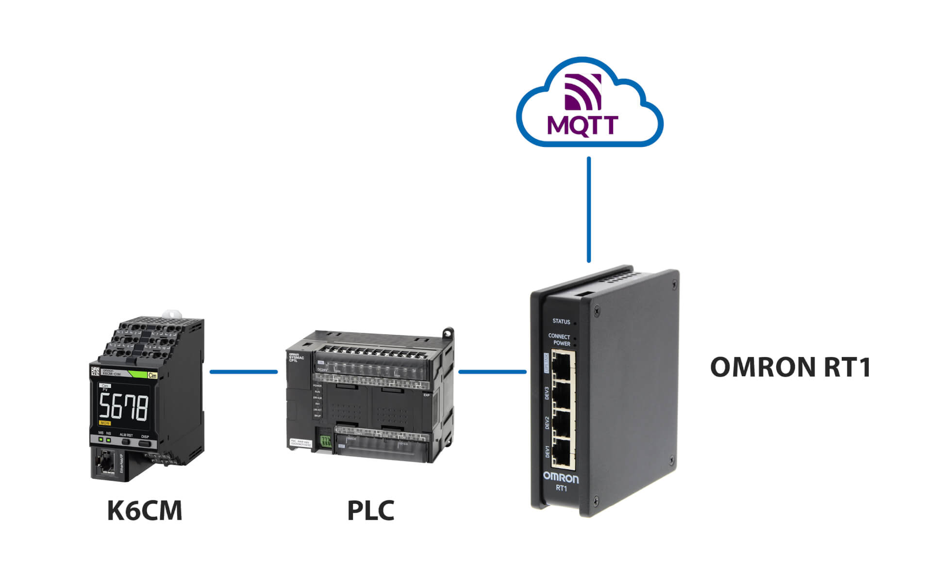
Benachrichtigungen und Fernüberwachung – ohne SPS
Diese Lösung mit Omron RT1 als Gateway ermöglicht Folgendes:
- E-Mail-/SMS-Benachrichtigungen, falls Anomalien vom K6CM erkannt werden
- Sichere Verbindung (verwaltet von RT1) zur Cloud, entweder über LAN oder über 4G-Verbindung
- Sichere Verbindung für die Fernüberwachung und Einrichtung des K6CM mithilfe der im Lieferumfang des Controllers enthaltenen Condition Monitoring Software
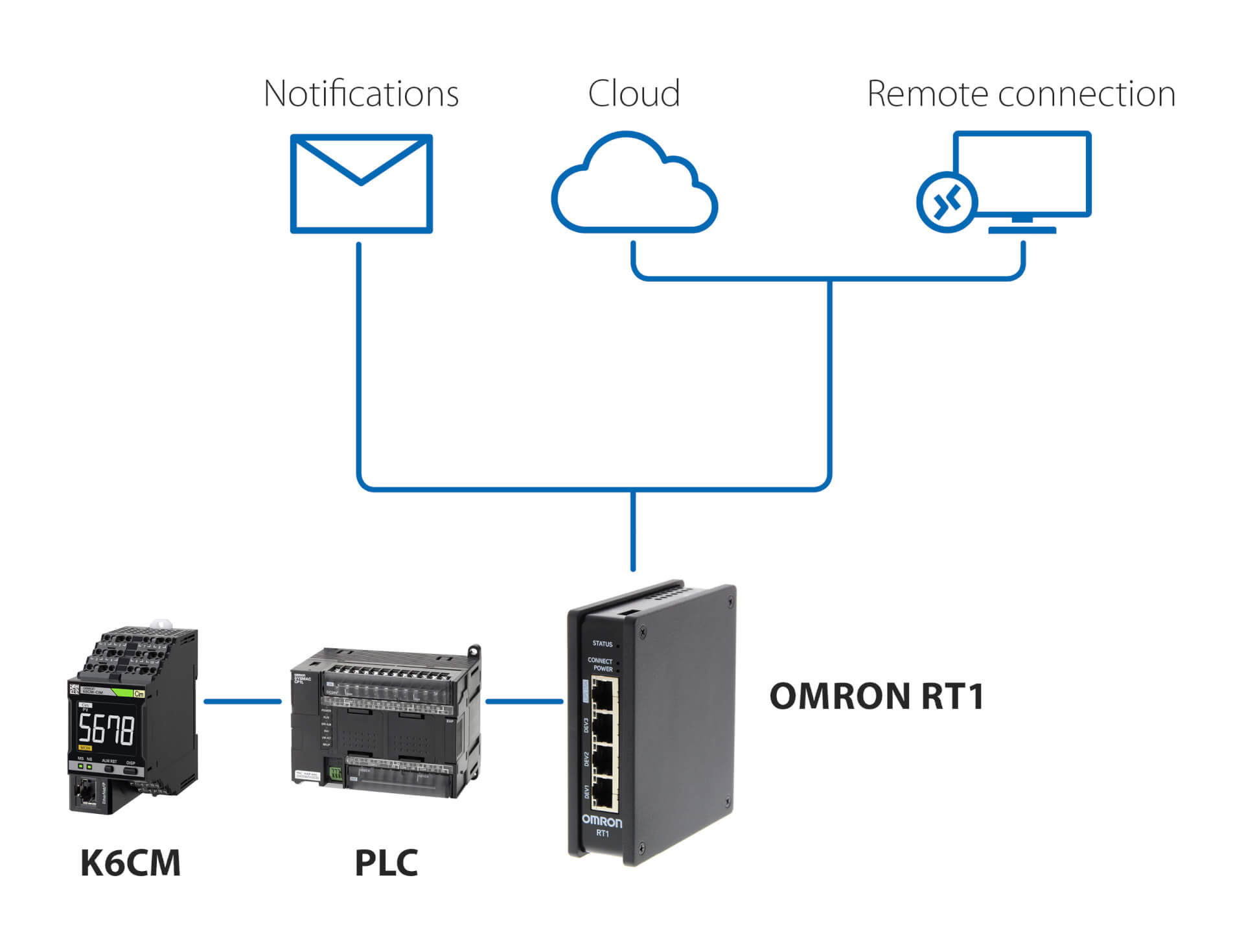
Benachrichtigungen und Fernüberwachung – mit SPS
Diese Lösung mit SPS und Omron RT1 als Gateway ermöglicht Folgendes:
- E-Mail-/SMS-Benachrichtigungen, falls Anomalien vom K6CM erkannt werden
- Sichere Verbindung (verwaltet von RT1) zur Cloud, entweder über LAN oder über 4G-Verbindung
- Sichere Verbindung für die Fernüberwachung und Einrichtung des K6CM mithilfe der im Lieferumfang des Controllers enthaltenen Condition Monitoring Software
Verbindung mit dem MQTT-Server
Zugehörige Produkte
-
Zustandsüberwachungsgerät für Motoren – Stromüberwachung
-
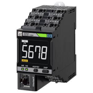
Zustandsüberwachungsgerät für Motoren – Vibrationsüberwachung
-
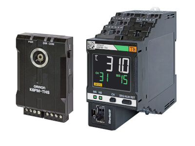
Thermografiebasierte Zustandsüberwachung
-
Zustandsüberwachungsgerät – Isolationsüberwachung
Downloads