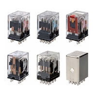
MY
Universalrelais-Familie für verschiedene Umgebungen und Anwendungen
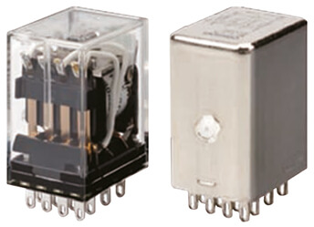
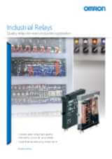
- Jedes Modell* der MY-Produktfamilie verfügt standardmäßig über ein transparentes Gehäuse, eine mechanische Anzeige, um den Status der Kontakte einfach überprüfen zu können, und eine LED, die nicht nur den ordnungsgemäßen Betrieb des Relais anzeigt, sondern auch zur sofortigen Identifizierung der Spulenspannungsart dient: Eine rote LED bedeutet AC-Spule (Wechselstrom), eine grüne LED bedeutet DC-Spule (Gleichstrom).
- 2,6 mm breite Pins sorgen für eine höhere Leitfähigkeit und einen geringeren Temperaturanstieg
- Das MY-GS-R ist das Highlight der Produktfamilie mit 2- und 4-poligen Modellen, die mit LED, Testknopf und Schutzbeschaltung ausgestattet sind. Die DC-Version hat dank des LED-Designs keine Polarität (ausgenommen Modelle mit Freilaufdiode)
- Erhältlich als hermetisch oder kunststoffversiegelte Relais, Modelle mit gegabelten goldbeschichteten Kontakten für kleinste Lasten
- Der Verdrahtungsaufwand kann im Vergleich zu herkömmlichen Sockeln mit Schraubklemmen um bis zu 60 %** reduziert werden. Durch den Einsatz des MY mit Sockeln mit „Push-In-Plus“-Klemmen (PYF-[]-PU) kann aufgrund der geringen Einsteckkraft die Verdrahtungszeit verringert werden.
* Sondermodelle sind ausgeschlossen
** Bei Verwendung von Sockeln mit „Push-in-Plus“-Klemmen
Produktabkündigung: März 2024 gilt NUR für EUROPA. Um weitere Informationen zu erhalten, laden Sie bitte diese Abkündigung herunter.
Spezifikationen & Bestellinfo
| Produkt | Mounting method | Usage | Poles | Rated carry current | Coil voltage | Operation voltage | Contact material | Contact description | Features | Terminal type | Beschreibung | |
|---|---|---|---|---|---|---|---|---|---|---|---|---|
|
|
With plug-in socket | General purpose | 2 | 10 A | 110 V | AC | Ag | DPDT | Transparent case, With mechanical indicator | Plug-in, Solder | Relais, Plug-in, 8-polig, DPDT, 7 A, mechanische Anzeige, 110/120 VAC |
|
|
|
With plug-in socket | General purpose | 2 | 10 A | 12 V | AC | Ag | DPDT | Transparent case, With mechanical indicator | Plug-in, Solder | Relais, Plug-in, 8-polig, DPDT, 7 A, mechanische Anzeige, 12 VAC |
|
|
|
With plug-in socket | General purpose | 2 | 10 A | 230 V | AC | Ag | DPDT | Transparent case, With mechanical indicator | Plug-in, Solder | Relais, Plug-in, 8-polig, DPDT, 7 A, mechanische Anzeige, 220/240 VAC |
|
|
|
With plug-in socket | General purpose | 2 | 10 A | 24 V | AC | Ag | DPDT | Transparent case, With mechanical indicator | Plug-in, Solder | Relais, Plug-in, 8-polig, DPDT, 7 A, mechanische Anzeige, 24 VAC |
|
|
|
With plug-in socket | General purpose | 2 | 10 A | 48 V | AC | Ag | DPDT | Transparent case, With mechanical indicator | Plug-in, Solder | Relay, plug-in, 8-pin, DPDT, 10 A, mechanical indicator, 48 VAC |
|
|
|
With plug-in socket | General purpose | 2 | 10 A | 110 V | DC | Ag | DPDT | Transparent case, With mechanical indicator | Plug-in, Solder | Relais, Plug-in, 8-polig, DPDT, 7 A, mechanische Anzeige, 100/110 VDC |
|
|
|
With plug-in socket | General purpose | 2 | 10 A | 12 V | DC | Ag | DPDT | Transparent case, With mechanical indicator | Plug-in, Solder | Relay, plug-in, 8-pin, DPDT, 10 A, mechanical indicator, 12 VDC |
|
|
|
With plug-in socket | General purpose | 2 | 10 A | 24 V | DC | Ag | DPDT | Transparent case, With mechanical indicator | Plug-in, Solder | Relais, Plug-in, 8-polig, DPDT, 7 A, mechanische Anzeige, 24 VDC |
|
|
|
With plug-in socket | General purpose | 2 | 10 A | 48 V | DC | Ag | DPDT | Transparent case, With mechanical indicator | Plug-in, Solder | Relay, plug-in, 8-pin, DPDT, 10 A, mechanical indicator, 48 VDC |
|
|
|
With plug-in socket | General purpose | 2 | 10 A | 110 V | AC | Ag | DPDT | CR circuit, LED, Test button, Transparent case, With mechanical indicator | Plug-in, Solder | Relay, plug-in, 8-pin, DPDT, 10 A, mechanical & LED indicators, Coil Surge Absorption, lockable push test button, 110/120 VAC |
|
|
|
With plug-in socket | General purpose | 2 | 10 A | 230 V | AC | Ag | DPDT | CR circuit, LED, Test button, Transparent case, With mechanical indicator | Plug-in, Solder | Relay, plug-in, 8-pin, DPDT, 10 A, mechanical & LED indicators, Coil Surge Absorption, lockable push test button, 220/240 VAC |
|
|
|
With plug-in socket | General purpose | 2 | 10 A | 24 V | DC | Ag | DPDT | Diode, LED, Test button, Transparent case, With mechanical indicator | Plug-in | Relay, plug-in, 8-pin, DPDT, 10 A, mechanical & LED indicators, with built-in diode for coil surge absorption, reverse polarity, lockable push test button, 24 VDC |
|
|
|
With plug-in socket | General purpose | 2 | 10 A | 110 V | DC | Ag | DPDT | Diode, LED, Test button, Transparent case, With mechanical indicator | Plug-in, Solder | Relay, plug-in, 8-pin, DPDT, 10 A, mechanical & LED indicators, Coil Surge Absorption, lockable push test button, 100/110 VDC |
|
|
|
With plug-in socket | General purpose | 2 | 10 A | 12 V | DC | Ag | DPDT | Diode, LED, Test button, Transparent case, With mechanical indicator | Plug-in, Solder | Relay, plug-in, 8-pin, DPDT, 10 A, mechanical & LED indicators, Coil Surge Absorption, lockable push test button, 12 VDC |
|
|
|
With plug-in socket | General purpose | 2 | 10 A | 24 V | DC | Ag | DPDT | Diode, LED, Test button, Transparent case, With mechanical indicator | Plug-in, Solder | Relais, Plug-in, 8-polig, DPDT, 7 A, mechanische und LED-Anzeige, Schutzbeschaltung, verriegelbarer Testdrucktaster, 24 VDC |
|
|
|
With plug-in socket | General purpose | 2 | 10 A | 110 V | AC | Ag | DPDT | LED, Test button, Transparent case, With mechanical indicator | Plug-in, Solder | Relais, Plug-in, 8-polig, DPDT, 7 A, mechanische und LED-Anzeige, verriegelbarer Testdrucktaster, 110/120 VAC |
|
|
|
With plug-in socket | General purpose | 2 | 10 A | 12 V | AC | Ag | DPDT | LED, Test button, Transparent case, With mechanical indicator | Plug-in, Solder | Relais, Plug-in, 8-polig, DPDT, 7 A, mechanische und LED-Anzeigen, verriegelbarer Testdrucktaster, 12 VAC |
|
|
|
With plug-in socket | General purpose | 2 | 10 A | 230 V | AC | Ag | DPDT | LED, Test button, Transparent case, With mechanical indicator | Plug-in, Solder | Relais, Plug-in, 8-polig, DPDT, 7 A, mechanische und LED Anzeige, verriegelbarer Testknopf, 220/240 VAC |
|
|
|
With plug-in socket | General purpose | 2 | 10 A | 24 V | AC | Ag | DPDT | LED, Test button, Transparent case, With mechanical indicator | Plug-in, Solder | Relais, Plug-in, 8-polig, DPDT, 7 A, mechanische und LED-Anzeige, verriegelbarer Testdrucktaster, 24 VAC |
|
|
|
With plug-in socket | General purpose | 2 | 10 A | 48 V | AC | Ag | DPDT | LED, Test button, Transparent case, With mechanical indicator | Plug-in, Solder | Relay, plug-in, 8-pin, DPDT, 10 A, mechanical & LED indicators, lockable push test button, 48 VAC |
|
Sie brauchen Unterstützung?
Wir helfen Ihnen gerne! Sprechen Sie uns an, und unsere Experten helfen Ihnen, die beste Lösung für Ihr Unternehmen zu finden.
Ihr Kontakt MY

Vielen Dank für Ihre Anfrage. Wir setzen uns umgehend mit Ihnen in Verbindung.
Es liegen zur Zeit technische Probleme vor. Ihre Übertragung war nicht erfolgreich. Entschuldigen Sie dies bitte und versuchen es später noch einmal. Details
Angebot für MY
Über dieses Formular erhalten Sie ein Angebot zu Ihrem ausgewählten Produkt. Bitte füllen Sie alle Felder aus, die diese * Markierung besitzen. Ihre persönlichen Daten werden natürlich vertraulich behandelt.
Vielen Dank für Ihre Angebots-Anfrage, die wir schnellstmöglich beantworten werden.
Es liegen zur Zeit technische Probleme vor. Ihre Übertragung war nicht erfolgreich. Entschuldigen Sie dies bitte und versuchen es später noch einmal. Details
Ausführungen
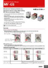
MY-GS-R - Miniature Power Relays Mechanical indicators added as a standard feature to our best-selling MY General-purpose relays
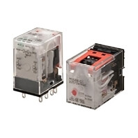
- MY-GS-R, das neueste Mitglied der MY-Familie, wird in einer vollständig automatisierten Fabrik hergestellt
- Reduziert in Verbindung mit der „Push-in-Plus“-Buchse den Verdrahtungsaufwand um 60 % (gemäß Messungen von OMRON).
- Der Aufdruck auf dem Klebeband der Spule zeigt die Spezifikation der Betriebsspule an
- Alle Modelle sind standardmäßig mit einer mechanischen Betriebsanzeige ausgestattet
- RoHS-konform, UL, CSA und IEC (VDE-Zertifizierung).
- Zum einfachen Prüfen des Kontaktstatus sind alle Modelle standardmäßig mit einer mechanischen Anzeige ausgestattet.
- Das MY-GS-R eignet sich für Anwendungen, bei denen ein zuverlässiges Relais benötigt wird. Das Standardmodell wird häufig in Verpackungsmaschinen für die Lebensmittel- und Getränkeindustrie eingesetzt
MY(S) - Miniature Power Relays
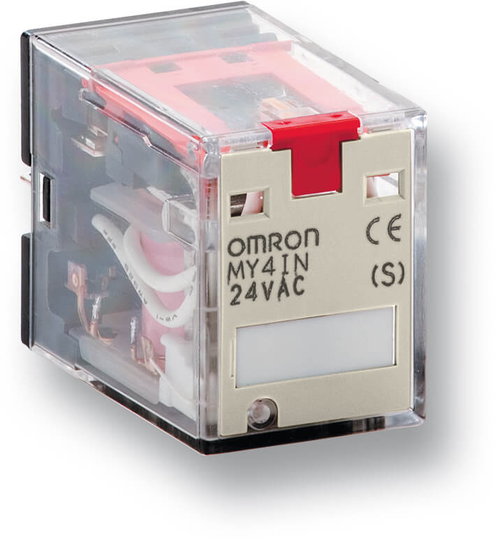
Vielseitiges Steckrelais, das Maßstäbe setzt
- Seit seiner Einführung wurde dieses Miniatur-Leistungsrelais über 1 Milliarde mal produziert und erfolgreich in vielen verschiedenen Anwendungen eingesetzt. Gabelkontakte sind optional erhältlich, um über die gesamte elektrische Lebensdauer eine zuverlässige Schaltung bei geringen Stromstärken zu gewährleisten. Umfassendes Sortiment von Buchsen, die durch Festschrauben, mit einer Klammer oder mit einer Klemmverbindung ohne Schrauben montiert werden können.
- Die MY-S-Modelle mit LED und Prüftaste haben sich dank visueller Anzeige und einfacher Prüffunktion zum Topseller entwickelt
- Die MY-S-Familie umfasst die MY4Z-Modelle mit Gabelkontakten für minimale Stromstärken
- Die MY-S-Relais kommen in der Gebäudeautomationsbranche häufig zum Einsatz, da sie für den Kunden die erste Wahl für Klimaregelungsanwendungen/Klimaanlagen und Fahrstühle sind
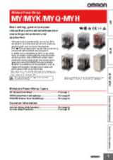
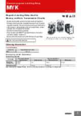
MYK - Miniature Power Latching Relays
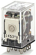
Magnetisches Verriegelungsrelais, ideal für Speicher- und Datenübertragungsschaltkreise
- Magnetisches MYK-Verriegelungsrelais, das bei geringem Stromverbrauch den Betriebsstatus der Kontakte beibehält
- Doppelt gewickeltes Verriegelungssystem mit Speicherung von Restmagnetismus. Die speziellen magnetischen Werkstoffe machen alterungsbedingte Veränderungen vernachlässigbar und sorgen so für eine lange durchgehende Haltezeit. Eigenschaften wie Kontaktfolge, Kontaktdruck usw. bleiben über die gesamte, lange Lebensdauer nahezu unverändert.
- Exzellente Vibrations-/Stoßfestigkeit
- Durch die eingebaute Betriebsanzeige lässt sich leicht erkennen, ob das Relais ein- oder ausgeschaltet ist
- Das MY2K wird auch in Schalttafeln bei Windenergie-Anwendungen eingesetzt
MYQ/MYH - Miniature Power Sealed Relays
Abgedichtete Relais, die unempfindlich gegenüber staubigen Umgebungen, korrosiven Gasen usw. sind.
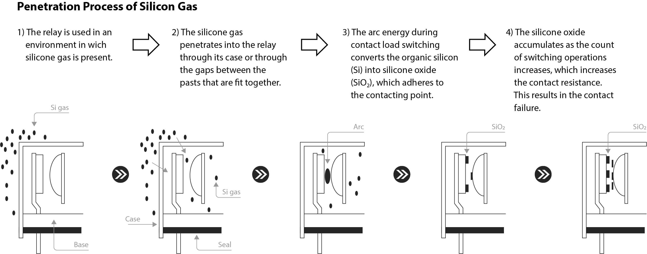
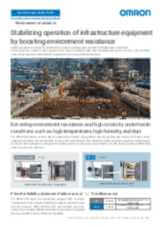
- In Umgebungen mit Staubbildung (z. B. wenn Form- und Schleifmaschinen in der Nähe sind) und in Anwendungsumgebungen, in denen kleine Insekten (z. B. Mücken oder Fliegen) vorhanden sind, können diese Fremdstoffe durch Lücken zwischen Teilen und durch die Belüftungsöffnungen des Relais in das Relais eindringen. Staub und Insekten verbleiben häufig im Inneren des Relais. Wenn diese dann an den Kontakten haften bleiben, kann dies zu Problemen wie Ausfall und Fehlfunktionen der Kontakte führen. Mit Kunststoff versiegelte Relais (MYQ) und hermetisch versiegelte Relais (MYH) sind unempfindlich gegenüber Umgebungseinflüssen.
- Auch für Umgebungen empfohlen, in denen korrosive Gase wie Chlor-, Schwefel- oder Silikongas erzeugt werden
- Sie sind außerdem unempfindlich gegenüber Umgebungen, in denen Salzschäden und Staub auftreten.
- Ausfälle der Relaiskontakte werden durch die äußerst luftdichte Bauweise vermieden
Videos

-

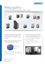
OMRON Relay Quality
Creating the perfect relays may seem like a straightforward task, but it’s a complex process that requires the most advanced manufacturing processes. This ensures that every component inside our relays are precisely assembled and protected from any outside contaminants. Ignoring this crucial step could jeopardize the reliability of the relays and compromise their switching activity. At times, machines can experience unplanned downtime, with the causes remaining elusive, in many cases restarting the machine or replacing the relays resolves the issue. OMRON determined that such incidents are primarily caused by inadequate contact conduction, which frequently results from dust caught between the contacts during manufacturing. OMRON's unique production techniques avoid poor conduction due to dust by providing standardized product design, producing the products in clean room with strict entry/exit control rules, and utilizing OMRON’s unique dust removal technology. This production technique are applied for all the OMRON relays especially the new ones introduced in the line up G2RV-ST/G3RV-ST, and MY-GS-R. Find out more about our new relays in our website: #MakeitOMRON #MakeitExcellent
02:30
OMRON Relay Quality
Creating the perfect relays may seem like a straightforward task, but it’s a complex process that requires the most advanced manufacturing processes. This ensures that every component inside our relays are precisely assembled and protected from any outside contaminants. Ignoring this crucial step could jeopardize the reliability of the relays and compromise their switching activity. At times, machines can experience unplanned downtime, with the causes remaining elusive, in many cases restarting the machine or replacing the relays resolves the issue. OMRON determined that such incidents are primarily caused by inadequate contact conduction, which frequently results from dust caught between the contacts during manufacturing. OMRON's unique production techniques avoid poor conduction due to dust by providing standardized product design, producing the products in clean room with strict entry/exit control rules, and utilizing OMRON’s unique dust removal technology. This production technique are applied for all the OMRON relays especially the new ones introduced in the line up G2RV-ST/G3RV-ST, and MY-GS-R. Find out more about our new relays in our website: #MakeitOMRON #MakeitExcellentZugehörige Produkte
-
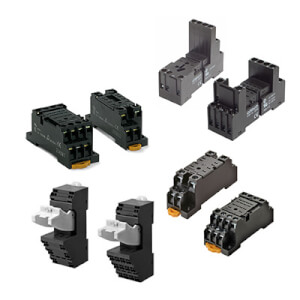
PYF ist das Sockelsortiment der MY-Relaisfamilie, das auch für Halbleiterrelais (Solid State Relais, SSR) und Zeitrelais geeignet ist.
Downloads
_miniature_power_relays_datasheet_en.jpg)
_series_(europe)_discontinuation_notice_en.jpg)
_discontinuation_notice_en.jpg)
_myk_myq_myh_miniature_power_relays_datasheet_en.jpg)
_discontinuation_notice_en.jpg)
n1-d2_and_my4(i)n1-d2_discontinuation_notice_en.jpg)